This blog post is going to teach you how to add an Inverter, Alternator charging via DC-DC Charger, and Solar charging to your OEM camper or RV that came factory installed with 50 amp shore power hookups.
This setup will allow for 120V appliances/devices to run on shore, generator, OR battery power. 240V appliances will run on Shore/Generator only (and will need a 120V/240V compatible breaker box (Not shown below).
This diagram features:
- 3000W Inverter Charger
- 400+ Amp Hours of Battery Storage Capacity
- 400W-1200W Solar Array Capacity
- Alternator Charging
- Shore Power Charging/Passthrough
50 Amp OEM Camper Electrical Upgrade Wiring Diagram
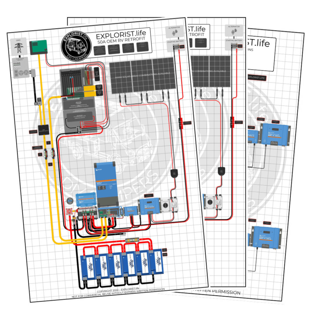
CLICK HERE TO PURCHASE THE HI-RES PRINTABLE PDF OF THIS DIAGRAM
50A Camper – Inverter w/ Solar & Alternator Charging Upgrade Shopping List
The following list will show you 98% of the items you need to install this system on your camper. If you need clarification on where something goes, please refer to the ‘Detailed Parts List’ below this consolidated shopping list. Also, you will need to refer to the solar array wiring diagrams at the bottom to add the appropriate solar array parts to your system below.
A NOTE ABOUT QUANTITIES
For the ‘Quantities’ in the below shopping list, each singular component is listed a quanty per each, wire is listed a quantity of feet, and heat shrink is listed as qty 1 = 2.25″.
For Example:
Qty 1 – Inverter Charger means you need to purchase 1 Inverter Charger
Qty 3 – 4/0 Wire means you need 3 feet of 4/0 wire. This may mean you need to buy 5ft from the product page
Qty 5 heat shrink means you need 5 pieces of 2.25″ heat shrink. This means you’ll need 5 x 2.25″ pieces of heat shrink for a total of 11.25″ of heat shrink.
Qty 8 – 2/0 x 5/16″ Wire lugs means you need 8 wire lugs… not 8 packs of wire lugs.
50A Camper – Inverter w/ Solar & Alternator Charging Upgrade Parts Detail
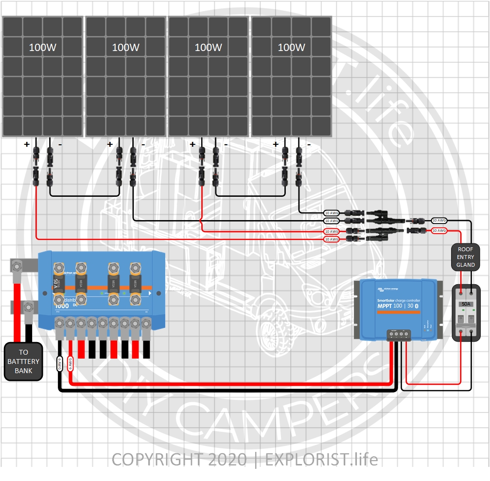
Choosing your Solar Panels & Charge Controller
The following section provides you with several different options for solar charging. The above parts list can remain completely unchanged and the diagram above can remain mostly unchanged except for the alterations noted by the diagrams below, but whatever solar array setup you choose below for your needs, these parts will need to be added to your shopping list. These are broken up by total solar wattage. As a general rule, you want to have twice as many watts of solar as you do amp hours of batteries. So, 300Ah Batteries = 600W solar. 400Ah Batteries = 800W solar. 600Ah Batteries = 1200W of solar. This is just a rule of thumb. Not a law.
400 Watts – 4x100W Solar Panels – 12V Battery Bank (Click to Expand)
600 Watts – 6x100W Solar Panels – 12V Battery Bank (Click to Expand)
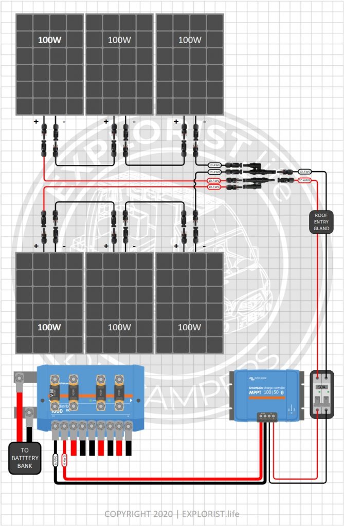
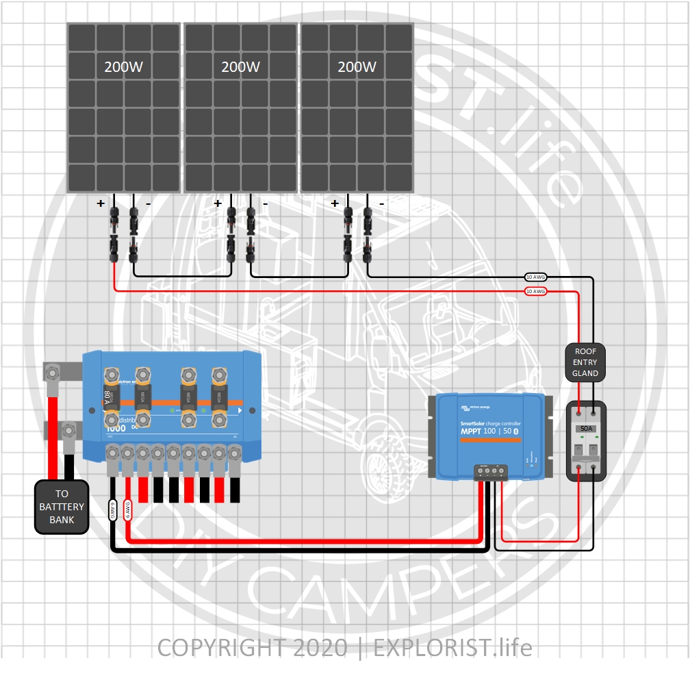
600 Watts – 3x200W Solar Panels- 12V Battery Bank (Click to Expand)
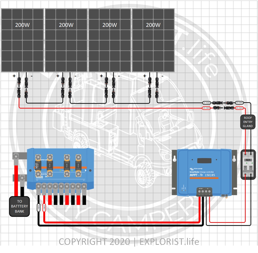
800 Watts – 4x200W Solar Panels- 12V Battery Bank (Click to Expand)
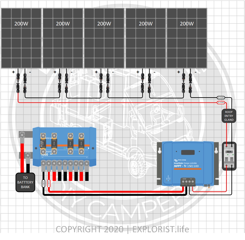
1000 Watts – 5x200W Solar Panels- 12V Battery Bank (Click to Expand)
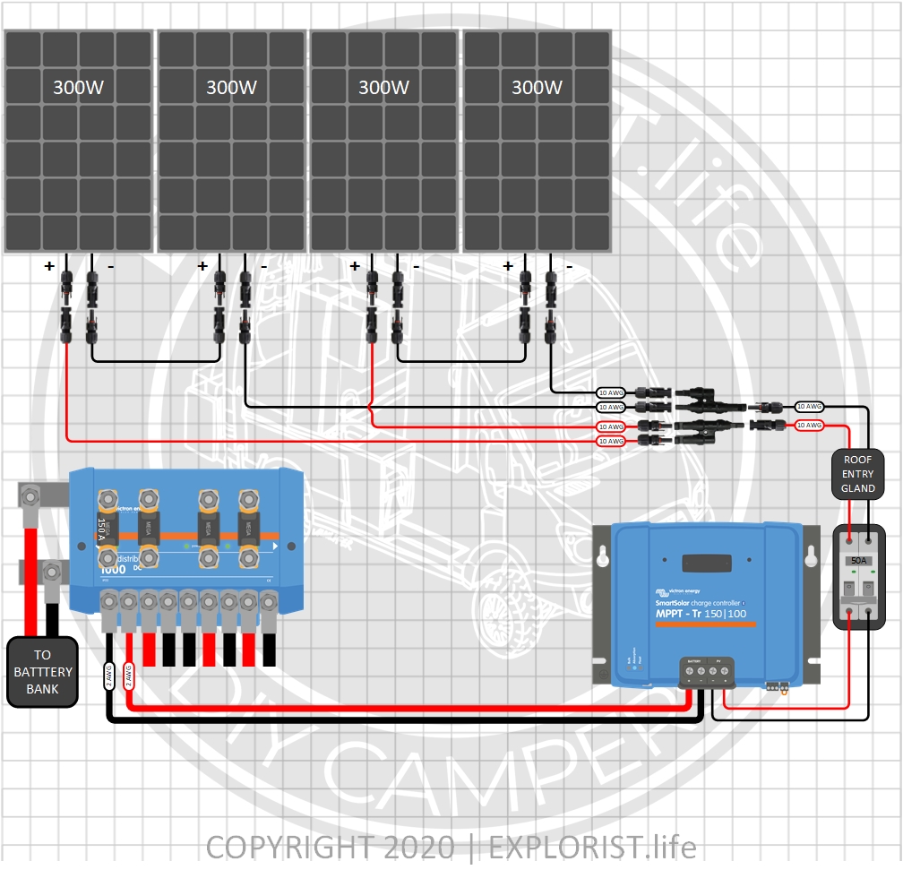
1200 Watts – 4x300W Solar Panels- 12V Battery Bank (Click to Expand)
How to Integrate a DIY Camper Electrical Upgrade with the OEM Wiring
The following section of this blog post will teach you how to integrate the wiring diagram and parts list above with your RV’s OEM electrical system.
Here is how the typical camper with 50A shore power hookups is wired:
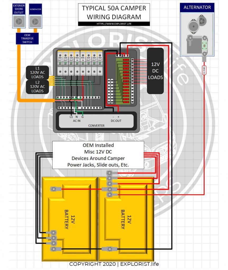
- The diagram above shows the typical bare-bones OEM RV/Camper with 50A shore power service.
- Shore power flows into the breaker box, powering the breaker box protected by a 50A breaker where 240v power is divided up into 2 legs of 120V power to power both sides of a breaker box
- One circuit is generally the Converter. The converter is usually built into the same enclosure that houses the breaker box (as shown) but is sometimes external. Either way, it’s wired in the same method.
- The converter converts the 120V AC power to 12V DC power which feeds the DC Fuse Block which powers the various DC devices around the camper (Lights, Fans, Etc..).
- From there, a positive and negative wire continues on to the house battery bank; usually two 12v batteries wired in parallel. These wires charge the batteries from shore power, and allow 12v devices to run when not connected to shore power.
- At the batteries, there are usually 2+ additional positive and negative wires heading off under the RV somewhere that are going to power additional DC circuits around the camper. These may be slide-outs, powered leveling jacks, and other ‘chassis’ items like that. These wires will likely have fuses in line to protect these wires coming from the battery.
- One of these wires is also likely the wire coming from the alternator to charge the house battery bank.
When the camper is NOT plugged in to shore power, all of the 12V DC appliances will run due to them still being connected to the batteries, but the 120V AC appliances will NOT operate because the converter is a one-way-street and will not convert 12V DC back to 120V AC. The charging from alternator is typically very slow (less than 10 amps) and should, generally, not be relied on to provide adequate power for recharging deeply depleted house battery banks.
In addition to wiring the components together, here is a breakdown of how the flow of power to the above diagram works.
WIRING THE INVERTER/CHARGER To Shore Power.
When connected to shore power or generator, power flows from shore power (or generator) to the inverter charger. This charges the batteries which feeds the DC fuse block and allows 50A shore power passthrough to power the 120v appliances. You will take the 6/4 wire that goes from the shore power inlet to the back of the AC distribution panel and instead, run that wire from the shore power inlet to the input of the Victron Multiplus.
Wiring the Inverter/Charger AC Distribution Panel
The 6/4 Wire from the AC Out of the Inverter/Charger will go to the same place that was just mentioned in the above step.
Wiring the Solar Panel Array to your Camper Electrical System
When charging from solar, the solar panels & charge controller charge the batteries. The batteries are connected to the DC fuse block allowing use of the 12v devices around the camper. The Inverter takes the 12V DC power stored in the batteries and converts it to 120V AC power to power the 120V AC items around the camper.
Replacing Stock Camper Batteries with Busbars
A positive and negative busbar take the place of the stock batteries in the stock battery location (assuming that upgrading batteries means you will not be able to store your new battery bank in the stock location). From the Lynx Distributor, power flows to these two busbars where power is then sent to all of the OEM installed components like the DC distribution block, power jacks, slides, etc.
50A Camper Converter
The OEM installed converter must be completely disconnected. It can remain installed, but the wires must be disconnected from both the AC and DC side of the power distribution center. These wires can usually be bundled up and stuffed next to the converter.
50A Camper Alternator Charging
You will likely have a wire charging your OEM batteries from the alternator. This wire will likely be somewhere in the 12 AWG range. This will either run directly from your starting battery isolator if this is a motorhome or from your 7-pin connector if this is a trailer. This needs to be disconnected completely. This diagram uses a 30A DC-DC Charger and the OEM installed wire will be too small. The 6 AWG wire in the diagram will take the place of the OEM wire you are to remove. In the case of a trailer, 6 AWG wire will need to be run all the way to the truck starting battery if alternator charging via DC-DC Charger is desired and disconnected by the hitch by means of an Anderson connector. If you do not wish to charge via the Alternator… this entire leg of charging can be omitted without ill effects.